Powering Stone Workshops: A Comprehensive Guide to Single-Phase Compressed Air Solutions
Compressed air is the unseen driving force in every modern stone workshop. From precision pneumatic chisels and efficient angle grinders to powerful sandblasters, all these tools rely on a constant and dependable supply of compressed air. A demand of around 40 CFM (approximately 1130 l/min) at a stable pressure of 6–8 bar is the norm, not the exception. The problem arises when the workshop, especially if located in a rural area, an older building, or simply without access to a “three-phase” supply, is limited to a standard single-phase electrical installation. Most compressors capable of meeting such demands are robust three-phase machines. Does this mean being forced to invest in noisy, fume-generating, and problematic-for-indoor-use combustion engine compressors (diesel or petrol)?
Fortunately, the answer is no! The lack of a three-phase supply is a challenge known worldwide – from rural Ireland and expansive areas of the USA to many other locations. However, there are proven, effective, and increasingly popular electric alternatives that allow you to enjoy adequate compressed air power without the costly and not always feasible upgrade of your electrical connection, and without the compromises associated with combustion engine compressors.
This article is a comprehensive guide to two main strategies for solving this problem, enriched with practical examples, tables, and diagrams. However, we must strongly emphasise: this is an informational and conceptual guide, not a DIY installation manual. The design, component selection, and installation of a compressed air system of this capacity, especially when operating on single-phase power in a non-standard manner, must always be carried out by qualified professionals in the pneumatic industry and certified electricians with the appropriate credentials. This is not only necessary to ensure optimal performance, equipment longevity, and warranty compliance, but above all due to legal regulations (e.g., concerning the technical supervision of pressure vessels – UDT in Poland, Pressure Systems Safety Regulations 2000 in the UK), health and safety standards (H&S), and technical norms. DIY experiments with high-pressure installations and high-current electricity are a direct path to costly failures, voided warranties, legal issues, and, most critically, serious risks to health and life. Investing in professional consultation and execution is fundamental to safe and efficient operation.
Solution 1: Combining Forces – Multi Single-Phase Compressor Systems
When a single single-phase compressor is insufficient and a “three-phase” supply is unavailable, the solution may be an intelligent combination of several smaller units working together to achieve the required output.
Concept
The idea is relatively simple: several smaller single-phase compressors operate in parallel, delivering compressed air to a shared, suitably large buffer tank (receiver). Their individual capacities combine to create the necessary flow. The receiver plays a crucial role as a pneumatic energy store, stabilising system pressure, while smart control (pressure switches set in cascade) optimises the operation of individual compressors, activating them only when needed.
Which Single-Phase Compressor Type to Choose – The Key to Success and Reliability
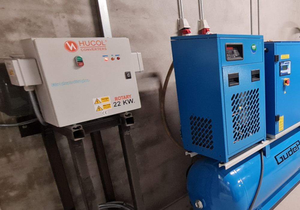
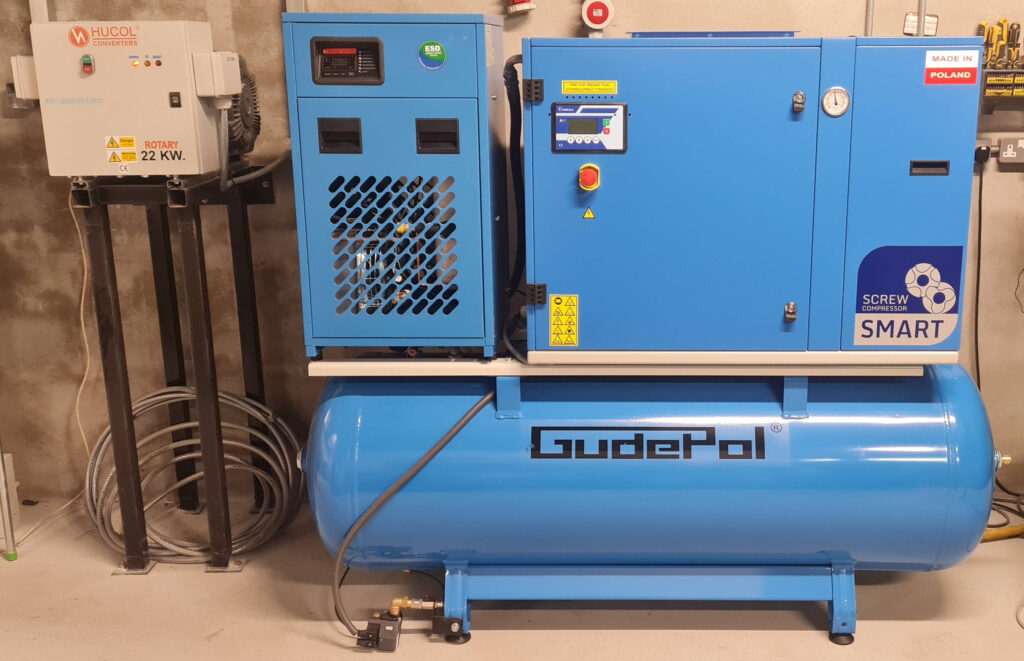
Choosing the right type of single-phase compressor is fundamental for the efficiency, working comfort, operating costs, and longevity of the entire system. For professional applications in a stone workshop, where work is often long, intensive, and requires a constant air supply, single-phase screw compressors are by far the best choice.
Why are screw compressors preferred?
» Higher Free Air Delivery (FAD): Screw compressors, compared to piston types of the same motor power, deliver more usable air. Piston compressor manufacturers often quote theoretical (swept volume/displacement) capacity, which can be 25-35% higher than the actual effective output. With screw compressors, this difference is significantly smaller, meaning more efficient energy use.
» Quieter and More Stable Operation: They generate considerably less noise and vibration, which is invaluable in workshops located near residential buildings, in noise-sensitive areas, or simply where many people are working. A typical screw compressor’s noise level is often 60-70 dB(A), whereas a piston compressor can be 80-95 dB(A) or more.
» Continuous Operation Capability (100% Duty Cycle): Most screw compressors are designed for non-stop operation without needing cooling breaks. This is a key limitation for many piston compressors, which often have a 50/50 (5 minutes on, 5 minutes off) or 60/40 duty cycle, potentially insufficient for intensive use.
» Longer Lifespan and Lower Failure Rate: The simpler design of the screw element (fewer moving parts compared to a piston compressor) translates to greater reliability and longer service intervals. Less wear on components results in lower maintenance costs.
» Cleaner Output Air: Screw compressors, especially oil-lubricated models equipped with high-quality oil separators, often deliver air with significantly lower residual oil content than piston compressors. This is important for tool longevity and the quality of some processes (e.g., painting, precision sandblasting).
» Smaller Size and Weight for Comparable Output: Often, a screw compressor of a given capacity will be more compact than its piston equivalent.
Single-phase piston compressors can be considered as a more budget-friendly initial option, but mainly for less intensive applications, where a higher noise level and the need for work breaks are acceptable. In the long run, for a professional workshop, investing in screw compressors usually proves more cost-effective.
Practical Example: For a stone workshop operating 8 hours a day, where pneumatic tools like grinders, hammers, or sandblasters are in continuous, intensive use, two single-phase 3 kW screw compressors connected in parallel will provide significantly greater reliability, pressure stability, higher energy efficiency, and working comfort (lower noise) than, for instance, three piston compressors of similar total motor power.
Step-by-Step Guide to Implementing a Multi-Compressor System
-
Precise Air Demand Analysis: This is fundamental. It’s not enough to know the catalogue demand of individual tools. You must consider:
» Actual average and peak consumption: How many tools of what type operate simultaneously at the busiest times? What is their utilisation factor (how much time per hour do they actually draw air)?
» Nature of demand: Is the demand relatively constant (e.g., a grinder operating for extended periods), or highly pulsed (e.g., a sandblaster with a large nozzle, an impact hammer, a pneumatic wrench)?
» Example: A pneumatic hammer might consume 200-300 l/min but operates intermittently. A sandblaster with a large nozzle might momentarily require as much as 800-1000 l/min. Sum the demand of tools that might operate concurrently and add a safety margin (typically 10-25% to cover leaks, future expansion, and unforeseen peaks). -
Compressor Selection – Number and Power:
» Choose single-phase compressors (decidedly screw type preferred) whose combined Free Air Delivery (FAD) – the actual amount of air delivered at a given pressure – slightly exceeds your maximum calculated demand. Don’t use motor power as the sole criterion; FAD is more important.
» Thoroughly check your electrical installation’s capacity – are the cable cross-sections and overcurrent protection ratings adequate for simultaneously powering several compressors? Ideally, each compressor should be connected to a separate electrical circuit with its own dedicated protection. Consult an electrician! -
Buffer Tank (Air Receiver) Selection – The Heart of the Pneumatic System:
» Crucial for pressure stability, energy efficiency, and compressor protection. The larger the receiver, the less frequent the compressor start/stop cycles (extending their lifespan and reducing energy consumption) and the smaller the pressure fluctuations in the network, noticeable by the tools.
» For tools with high, pulsed air demand (e.g., sandblasters), the receiver must be sufficiently large to “buffer” these peaks and ensure smooth operation.
» General receiver sizing rules:
» For fixed-speed compressors (like most single-phase units): 6-10 litres of receiver capacity for every 1 CFM (approx. 28.3 l/min) of total compressor output.
» Another method: Receiver capacity (in litres) = (Total compressor output in l/s * 15) / (Acceptable pressure drop in bar).
» For shift work or intensive use, it’s always better to choose a receiver slightly larger than indicated by minimum calculations.
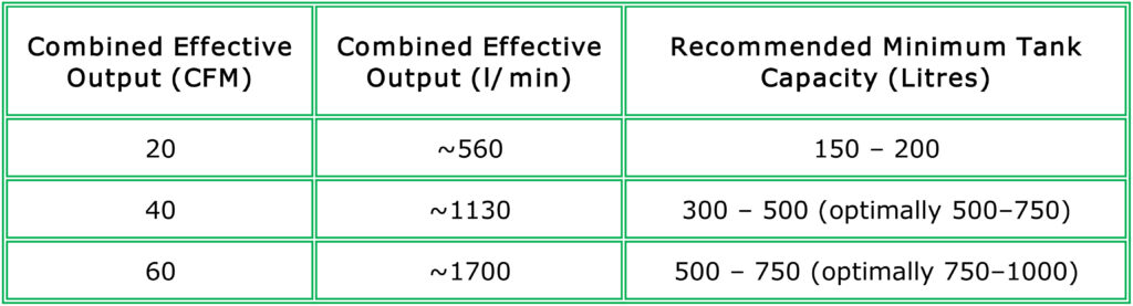
» Example: For a total demand of 40 CFM (approx. 1130 l/min), a 500-litre receiver would be a good choice (40 CFM * 28.3 l/min/CFM ≈ 1132 l/min. 1132 l/min / 60 s/min ≈ 18.8 l/s. Capacity ≈ 18.8 * 15 / 1 bar ≈ 282 litres – this is a minimum, more is recommended). For applications with very uneven demand or to ensure longer operating time if one compressor fails, consider a 750-litre receiver or even larger. Remember that receivers of certain parameters are subject to inspection (e.g., PSSR 2000 in the UK).
Indicative Receiver Sizing Table
(remember, these are minimum values; always consult a specialist!):
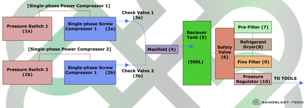
Block Diagram of a Multi-Compressor System (Example for two compressors)
Description of Key Multi-Compressor System Elements (with application examples)
-
Pressure Switch: (1a, 1b)
The “brain” controlling an individual compressor’s operation. In a multi-compressor system, cascade (sequential) setting of pressure switches is key to optimising energy use and evenly loading the compressors.
Example: Compressor No. 1 (lead) starts when receiver pressure drops to 6.5 bar and stops at 8 bar. Compressor No. 2 (lag) starts if pressure falls below 6.2 bar (despite No. 1 running) and also stops at 8 bar. This ensures the second compressor only runs when truly needed. More advanced systems might use a central controller. -
Single-Phase Compressor (Screw type preferred): (2a, 2b)
The heart of the system, responsible for producing compressed air. As mentioned, screw models are preferred for efficiency and durability.
Example: Two 3kW screw compressors, each delivering around 350-400 l/min FAD at 8 bar, can together supply most tools in a medium-sized stone workshop. -
Check Valve (Non-Return Valve): (3a, 3b)
An essential component fitted to each compressor’s outlet, before the manifold connection. It prevents compressed air from the receiver or a running compressor from flowing back into a non-operating unit. It also protects against pressure “feedback” between compressors and allows for their independent operation. -
Manifold: (4)
A specially designed distributor or suitably sized pipe section that collects compressed air from all compressor outlets and directs it via a single, common pipe to the buffer receiver. It should be made of corrosion-resistant material (e.g., stainless steel, brass, suitably protected galvanised steel) and have a diameter ensuring minimal pressure loss at maximum flow. -
Air Receiver (Buffer Tank): (5)
Performs several crucial functions:
» Stores compressed air, creating a reserve to meet peak demand.
» Dampens pressure pulsations, especially from piston compressors, providing a more stable supply to tools.
» Allows compressed air to cool, causing some of the entrained water and oil to condense out.
» Reduces the frequency of compressor start/stop cycles, which decreases wear and saves energy.
Must be equipped with a pressure gauge, safety valve, and condensate drain (manual, or much more conveniently and effectively, automatic – e.g., float, timed, or electronic level-controlled). -
Safety Valve: (6)
An absolutely critical safety component, required by regulations (e.g., Pressure Systems Safety Regulations 2000 in the UK). Mounted directly on the receiver (or in its immediate vicinity). In case of pressure switch failure and uncontrolled pressure rise above the receiver’s maximum allowable working pressure, the safety valve opens automatically, releasing excess air and protecting the receiver and entire system from rupture. It must be correctly sized for the working pressure and receiver capacity and regularly inspected and certified. -
Pre-Filter (Water/Particle Separator): (7)
The first stage of air treatment after the receiver. Removes larger solid particles (rust, scale) and bulk condensed water and oil that may have separated in the receiver. Protects subsequent, more sensitive system components (dryer, fine filters). -
Air Dryer: (8)
Compressed air always contains water vapour. The amount depends on the temperature and humidity of the air drawn in by the compressor. When compressed and cooled, water vapour condenses, forming liquid water in the system. This water leads to corrosion of pipes and tools, degrades work quality (e.g., in painting, sandblasting, causing streaking), can block nozzles, and may freeze in external pipework in low temperatures. The most common type in workshops are refrigerant (fridge) dryers, which cool the air to a pressure dew point (typically +3°C to +5°C), causing most of the moisture to condense out. For more demanding applications, adsorption dryers are used. -
Fine Filter (Coalescing – Oil Removal): (9)
Even the best oil-lubricated compressors (screw or piston) introduce some oil mist into the compressed air. A coalescing filter is designed to remove these fine oil particles and very small solid particles that may have passed through the pre-filter or dryer. It provides air of high purity, protecting tools and processes. For specific applications (e.g., paint spraying, breathing air), additional activated carbon filters may be needed to remove oil vapours and odours. -
Pressure Regulator with Gauge: (10)
Allows precise setting and maintenance of the required working pressure for specific tools or sections of the pneumatic system. Too high pressure can damage tools, increases air consumption, and is dangerous; too low pressure significantly reduces their performance. Each take-off point or group of tools should have its own regulator.
Advantages and Disadvantages of the Multi-Compressor Solution
Advantages:
» Achieve high total output on single-phase power: The main goal is met.
» Scalability: The system can be relatively easily expanded in the future by adding more compressor units as demand grows.
» Redundancy and increased reliability: Failure of one compressor does not completely paralyse workshop operations – the others can continue to operate, albeit at reduced capacity.
» Flexible operation and potential energy savings: Thanks to cascade control of pressure switches, only those compressors (or as many compressors) currently needed to meet demand are running. At low demand, only one unit may operate.
» Lower start-up load on a single electrical circuit: Starting several smaller motors is gentler on the electrical network (smaller current spikes) than attempting to start one very large single-phase motor of comparable total power.
Disadvantages:
» Greater system complexity: Requires careful design of pneumatic and electrical connections and the control system (pressure switches, possibly a central controller).
» More components to service and maintain: Each compressor requires individual attention (e.g., regular oil and filter changes in screw compressors).
» Potentially higher purchase cost for several smaller units compared to one large three-phase compressor of the same total capacity (however, this should be compared to the cost of a possible three-phase supply upgrade).
» Takes up more physical space in the compressor room.
» Need to ensure adequate ventilation for each compressor to dissipate the heat they generate.
Solution 2: Phase Conversion Magic – Powering a Three-Phase Compressor from a Single-Phase Supply using a Phase Converter
A second, increasingly popular, and often more technically elegant approach is to use a specialist device that “tricks” a standard, efficient three-phase compressor into running on a single-phase supply. This involves phase converters, predominantly Variable Frequency Drives (VFDs) and, as a more classic alternative, Rotary Phase Converters (RPCs/RTs).
A. Variable Frequency Drive (VFD)
Concept
A Variable Frequency Drive (VFD, often colloquially called an inverter) is an advanced power electronics device. Its primary task in this application is to take single-phase AC power from the mains, internally convert it to DC power in an intermediate circuit, and then generate from this DC power a perfectly symmetrical, three-phase AC voltage of adjustable frequency and amplitude. It is this three-phase output voltage that powers the standard three-phase asynchronous motor driving the compressor.
Step-by-Step Guide to Implementing a VFD System
-
Selecting a Three-Phase Compressor:
» Typically, this will be an efficient three-phase screw compressor, which is the standard for industrial and professional workshop applications requiring continuous operation and high-quality air.
» Choose a model with motor power (kW or HP) and FAD (in CFM or l/min) that precisely matches the workshop’s calculated demand. -
Selecting a Variable Frequency Drive (VFD): This is the key, often most expensive, and most demanding component of this solution.
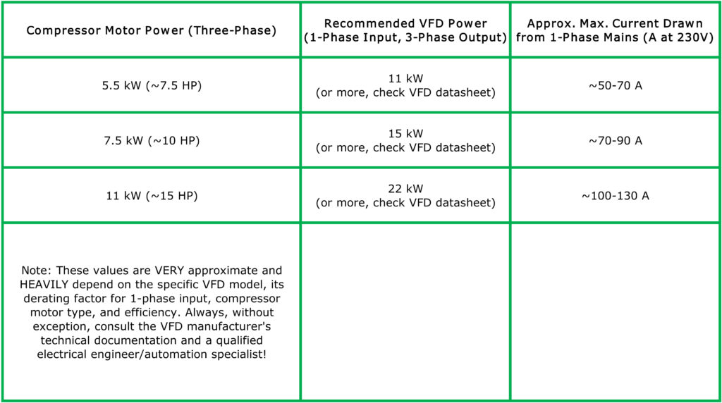
» VFD Power Rating (Derating/Oversizing): The VFD must be correctly sized for the compressor motor’s nominal power. Furthermore, for motors with a heavy starting torque or those operating under constant, full load (as in most compressors), it is absolutely essential to SIGNIFICANTLY OVERSIZE THE VFD relative to the motor power when the VFD is powered from a single-phase supply. VFD manufacturers often specify a “derating” factor (reduction in permissible output power) for single-phase input. A common rule of thumb is that a VFD powered from single-phase can drive a three-phase motor with a nominal power of about 50-60% of the VFD’s own nominal power rating. This means for a 7.5 kW compressor motor, you should select a VFD with a nominal power rating of at least 11 kW, and often even 15 kW, to ensure reliable operation and prevent VFD overheating. Always check the specific model’s technical documentation for its single-phase input capability and maximum permissible three-phase motor power in this mode.
» VFD Input Current: It is imperative to ensure that the single-phase electrical installation (cable cross-sections, overcurrent protection devices) can supply the current required by the VFD to power the three-phase motor. The current drawn by the VFD from the single-phase mains will be significantly higher (approximately at least 1.73 times higher, plus VFD losses) than the current on each of the three-phase output lines supplying the motor. This demands a very robust and high-capacity single-phase supply.
» Additional VFD Features: Modern VFDs offer many benefits:
» Soft Start: The VFD gradually increases the voltage and frequency supplied to the motor, significantly reducing a_start-up current. This is very beneficial for a single-phase network, which is more sensitive to large current spikes.
» Motor Speed Control Capability: Although the primary goal here is phase conversion, a VFD inherently allows motor speed to be varied by changing the output frequency. In practice, for standard fixed-speed compressors, the VFD will likely operate at a set, constant output frequency (e.g., 50 Hz). However, some compressors are available with motors specifically designed for VFD operation in variable speed mode (so-called VSD – Variable Speed Drive compressors), allowing perfect matching of compressor output to instantaneous air demand and significant energy savings.
» Built-in Motor Protection: Many VFDs have advanced motor protection features against overload, phase loss (on the output), over/undervoltage, phase-to-phase short circuit, earth fault, etc.
» Input and Output Voltage: The VFD must be suitable for the single-phase voltage available in the workshop (e.g., 230V in the UK/Europe) and generate a three-phase voltage appropriate for the compressor motor (e.g., 3x230V or 3x400V – this depends on how the motor windings are connected – star or delta – and the VFD configuration). Most three-phase motors in Europe are designed for 3x400V (star connection) or 3x230V (delta connection). A VFD powered from 1x230V typically generates 3x230V at its output, meaning the compressor motor must be connected in delta.
Indicative VFD Sizing Table (for screw compressors, with significant recommended oversizing for single-phase input):
Connection Diagram

Description of Key VFD System Elements
» Variable Frequency Drive (VFD): (3)
As described above, the heart of the power conversion system. Requires careful selection, installation in a suitable (often ventilated and dust-protected) enclosure, and correct configuration of dozens of parameters (e.g., V/f characteristic or vector control, acceleration/deceleration ramp times, current limits, motor protection settings, control input/output configuration).
Example: In a stone workshop needing to power a robust 7.5 kW screw compressor, where only a 230V single-phase line of adequate capacity (e.g., protected by a C63A MCB or higher) is available, a 15 kW VFD specifically designed or configured for single-phase input might be considered.
» EMC/RFI Filters and Output Chokes: (2, 4)
VFD operation, due to fast switching of power transistors, can generate high-frequency electromagnetic interference (EMI/RFI) that may adversely affect other electronic devices in the workshop (e.g., PLCs, radios, computers) and be emitted into the supply network. EMC/RFI filters installed at the VFD input help minimise this interference. Output (motor) chokes installed between the VFD and the motor reduce the rate of voltage rise (dv/dt), protect motor insulation, reduce bearing currents, and limit radiated interference from long motor cables. Their use is often recommended or required by VFD manufacturers and relevant standards.
» Main Single-Phase Line Protection and Motor Protection: (1, 5)
Essential for protecting the VFD and motor from the effects of short circuits and prolonged overloads. Must be precisely selected according to the VFD and motor technical documentation and local electrical regulations. VFDs themselves have many motor protection functions, but external protection is often required or recommended as an additional safeguard.
» Three-Phase Compressor (Usually Screw Type): (6, 7)
A standard, efficient compressor unit that, thanks to the VFD, can operate where a three-phase supply is unavailable. Many modern screw compressors are factory-fitted with their own microprocessor controller that manages compressor operation (e.g., load/unload cycles, oil temperature). It must be ensured that this controller will cooperate correctly with the motor powered by the VFD (e.g., no conflicts in control logic).
» Air Treatment System (Receiver, Dryer, Filters, Regulator): (8)
Analogous to Solution 1, these components are essential for preparing compressed air of the appropriate quality and pressure for the tools. Often, a three-phase compressor is already integrated with its own receiver and basic pressure control system.
B. Rotary Phase Converters (RPC/RT)
In the context of powering three-phase compressors from a single-phase supply, alongside the increasingly popular VFDs, it’s worth knowing about a more classic alternative: rotary phase converters (RPCs or RTs).
Concept
A Rotary Phase Converter (RPC) is an electromechanical device. At its heart is a special three-phase motor, called an “idler motor/generator,” and a set of capacitors. When single-phase power is connected to two windings of this idler motor and it is appropriately excited using start capacitors, the motor begins to rotate. Voltage is then induced in its third, unpowered winding, thus creating an “artificial” third phase. Together with the two “live” phases from the single-phase supply (or suitably transformed), this creates a three-phase system that can power the three-phase motors of connected machines.
Advantages of Rotary Phase Converters
» Can power multiple three-phase machines simultaneously: One appropriately sized RPC can supply several different three-phase machines in a workshop (e.g., a compressor, saw, milling machine), provided their total power demand does not exceed the RPC’s capacity.
» Simpler construction and potentially greater robustness in harsh conditions: These are more electromechanical than electronic devices, which can translate to greater resistance to surges, dust, or temperature fluctuations compared to sensitive VFD electronics.
» Good handling of motors with heavy starting torque: RPCs are generally well-suited for starting induction motors under load, typical of piston compressors or some workshop machinery.
» Independence from machine’s electronic controls: RPCs provide “raw” three-phase power, not interfering with a machine’s factory control systems.
Disadvantages and Limitations of RPCs
» Lower energy efficiency: The RPC’s idler motor draws current (often significant) even when none of the connected three-phase machines are operating (idle running). This generates constant energy losses and higher electricity bills.
» Noise and vibration: The running idler motor generates noise and vibration, which can be intrusive.
» Weight and size: RPCs are typically much larger and heavier than VFDs of comparable “processed” power.
» No motor speed control capability: RPCs supply three-phase voltage at a fixed mains frequency (e.g., 50 Hz), so there is no possibility of smooth motor speed regulation.
» Less precise phase voltage balancing: The voltage on the “generated” phase can fluctuate depending on the RPC’s load. Significant voltage imbalance (phase unbalance) can be harmful to some three-phase motors and sensitive electronics controlling modern machines.
» Need for careful selection of capacitors (start and run) to ensure optimal operating parameters and minimise voltage imbalance.
» For compressors with very heavy starting torque (e.g., some large piston compressors), significant oversizing of the RPC relative to the compressor motor’s nominal power may be necessary.
Comparison: VFD vs. Rotary Phase Converter (RPC)
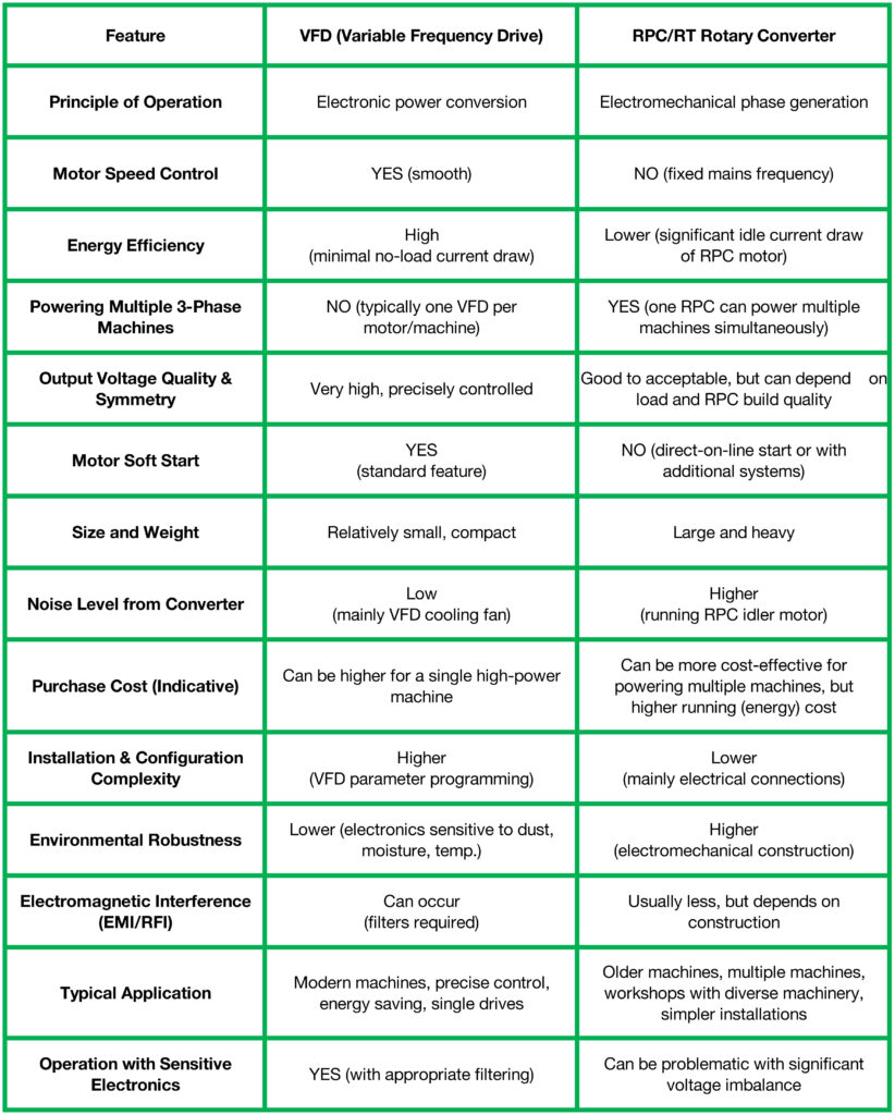
Rotary phase converters (RPCs/RTs) are a proven, albeit more “classic,” technology that still finds application, particularly where several different three-phase machines need to be powered from a single source, and precise speed regulation or the highest energy efficiency are not priorities. In modern workshops, where energy saving, quiet operation, the ability to precisely control motor parameters, and powering single, advanced machines (like a modern screw compressor) are key, a Variable Frequency Drive (VFD) is generally the more technologically advanced solution offering more benefits, despite a potentially higher initial cost and greater installation demands. The choice always depends on the specific workshop’s needs, the type and number of machines to be powered, the available budget, and user expectations.
Advantages and Disadvantages of Phase Converter Solutions (General for VFD and RPC)
Advantages (more prominent with VFDs):
» Ability to use standard, highly efficient three-phase compressors: Access to a wide range of professional machines, often cheaper and more reliable than their high-power single-phase counterparts.
» Potentially more compact solution than a multi-compressor system of the same total output (one larger compressor instead of several smaller ones).
» Advanced features (especially VFDs): Soft start, precise control, built-in motor protection, potential for speed regulation (leading to energy savings in VSD systems).
» Quieter overall system operation (if using a three-phase screw compressor) compared to, e.g., a system of multiple piston compressors.
Disadvantages (varying between VFDs and RPCs):
» Purchase cost of the converter: A good quality VFD or a suitably sized RPC can be a significant expense.
» Very high demands on the capacity and stability of the single-phase line: The current drawn from the single-phase mains can be very large, requiring thick cables and robust protection. Not every single-phase installation can handle this.
» Installation, configuration, and possible programming (VFD) require specialist knowledge and experience.
» Potential issues with electromagnetic interference (EMI/RFI) – mainly with VFDs: If the system is not properly designed and installed (filters, screening).
» Sensitivity of VFD electronics to power quality and adverse environmental conditions (temperature, humidity, dust). RPCs are generally more robust.
» Lower energy efficiency and noise in the case of RPCs.
Other Key Considerations – A Holistic Approach to the Compressed Air System
Regardless of the chosen strategy (multiple single-phase compressors or a phase converter with a three-phase compressor), several aspects are universal and absolutely critical for the success, efficiency, and safety of the entire system:
» Compressed Air Quality is King: In stonemasonry, where dust is ubiquitous and the precision and reliability of tools are paramount, supplying clean and dry air is fundamental. Investing in a good quality air treatment system – meaning a correctly sized dryer (refrigerant type for most workshop applications, or adsorption type for very high dryness requirements) and multi-stage filtration (pre-filter/cyclone separator, fine/coalescing filter for oil removal, possibly an activated carbon filter) – will pay for itself many times over in the form of longer pneumatic tool life, fewer breakdowns, higher quality work (e.g., no moisture problems in sandblasting or painting), and lower maintenance costs.
» Pneumatic Installation Design – Pipes are More Than Just Pipes:
» Correct internal pipe diameter: Too small a diameter leads to large pressure drops along the installation, forcing compressors to operate at a higher, unnecessary pressure in the receiver (which means greater energy consumption). The required diameter should be calculated based on flow rate and installation length.
» Pipe material: It is best to use systems specifically designed for compressed air made of aluminium (lightweight, easy to install, corrosion-resistant, smooth internal surface), copper, or stainless steel. Avoid ordinary black steel without adequate internal anti-corrosion protection, as rust products will contaminate the air and tools. Plastic pipes must be specifically rated for compressed air and resistant to oil and pressure.
» Installation layout: In larger workshops, a ring main (loop) system is often used, which provides more even pressure distribution and supply from two directions to each take-off point. For smaller workshops, a branched layout may suffice.
» Minimising bends and using gentle curves: Every sharp bend (90° elbow) causes pressure loss. Where possible, use bends with a larger radius.
» Correct slopes and condensate drain points: Pipework should be run with a slight slope (approx. 1-2%) in the direction of air flow, and manual or automatic condensate drains should be installed at the lowest points of the installation and at the ends of long runs.
» Compressor(s) Location and Ventilation – Key to Long Service Life:
» Compressors (especially larger screw units operating continuously) generate significant amounts of waste heat. Effective ventilation of the room where they operate (the “compressor room”) must be ensured to prevent them from overheating, which shortens their lifespan and can lead to emergency shutdowns. Adequate cool air intake and hot air exhaust must be provided.
» If possible, compressors should be located in a clean, dry, and cool area, away from major sources of stone dust (or in a suitably ventilated and filtered sound-dampening enclosure). Dust drawn in from the environment contaminates the compressor’s air filters and can enter the lubrication system.
» Regular Maintenance – The Guarantee of Reliability and Efficiency:
» Every component of the compressed air system requires regular attention and maintenance according to the manufacturer’s recommendations (O&M Manual – Operation and Maintenance Manual). This includes, among other things: changing oil and oil/air filters in screw compressors, checking and cleaning intake filters, checking and emptying condensate drains (in the receiver, dryer, on the installation), periodically checking belt tension (if applicable), testing the safety valve (trial lift, certification), replacing line filter elements, checking the entire installation for leaks (leaks are a major source of energy loss!), and monitoring the correct operation of the dryer. It is advisable to keep a service log for the entire system.
Professionalism Above All: Safety, Compliance, and Expert Knowledge
We now reach a point that cannot be overemphasised. This article, despite striving to be as detailed and helpful as possible, is merely a guide to potential technical solutions and concepts. Under no circumstances does it constitute instructions or recommendations for the independent design, component selection, and installation of advanced compressed air systems, especially when modifications to the electrical supply and operation with high-pressure equipment and high-current electricity are involved.
Why is it so important to entrust these tasks to professionals?
» Legal Requirements and Technical Standards:
» Pressure Vessels: In the UK (and many other EU countries and worldwide), compressed air receivers of a certain capacity and pressure-volume product are subject to stringent regulations regarding technical inspection (e.g., Pressure Systems Safety Regulations 2000 (PSSR) in the UK, requiring a Written Scheme of Examination and regular inspections by a competent person). They require appropriate conformity certificates (e.g., CE marking with a declaration of conformity to the Pressure Equipment Directive (PED) 2014/68/EU), regular inspections, pressure tests, and safety valve certification. A professional company specialising in pneumatic systems will ensure the selection and installation of a receiver compliant with these requirements and assist with inspection procedures.
» Electrical Installations: Must be designed and executed in accordance with current standards (e.g., BS 7671 IET Wiring Regulations in the UK) and legal requirements, by persons with appropriate qualifications and electrical credentials (e.g., NICEIC, NAPIT registered electricians). This applies particularly to installations supplying VFDs or multi-compressor systems, which require precise selection of protection devices and cable sizes.
» Health and Safety at Work (H&S): Employers have a legal duty to provide safe and healthy working conditions. A correctly designed, installed, protected, and regularly maintained compressed air system is a key element of this safety. Improper solutions can create serious hazards.
» Technical Complexity and Need for Specialist Knowledge:
» Correct selection of all system components: Choosing the right type and size of compressors, receiver, dryer, filters, VFD/RPC, pipe diameters, fittings, electrical protection – all this requires specialist knowledge, experience, and often complex engineering calculations.
» Electrical and pneumatic calculations: Analysis of the existing single-phase installation’s load capacity, selection of cable cross-sections and protection ratings, calculation of pressure drops in the pneumatic system, sizing of pipework to ensure optimal flow.
» Ensuring compatibility and correct interaction of all system components.
» VFD configuration and programming: Optimal setting of dozens of VFD parameters is a task for an automation specialist or an electrician experienced in drives, to ensure efficient, safe, and reliable operation of the compressor motor.
» Risks Associated with Unprofessional DIY Actions:
» Serious equipment failures: Incorrect selection or installation can lead to rapid and costly damage to expensive components (e.g., burning out the compressor motor, damaging the screw element, VFD failure).
» Low efficiency and high operating costs: A poorly designed system will be energy inefficient (e.g., excessive pressure drops, frequent compressor cycling, leaks), resulting in high electricity bills and frequent repairs.
» Direct safety hazards: High-pressure compressed air leaks (risk of injury from the air jet or flying debris), risk of receiver rupture (consequences can be catastrophic), electric shock, fire risk – these are all real dangers with an unprofessional approach.
» Insurance problems: In the event of an accident or failure caused by an unprofessionally installed or modified system, the insurer may refuse to pay out.
» Legal consequences: Operating an installation non-compliant with regulations and safety standards can lead to financial penalties from relevant supervisory bodies (e.g., HSE in the UK), and in the event of an accident, even civil and criminal liability.
Therefore, always and without exception, you should:
-
Commission the design of the entire compressed air system to a specialised company or an experienced designer/specialist in compressed air technology.
-
Entrust all work related to the electrical installation (connecting compressors, VFDs/RPCs, installing protection, carrying out tests) to a certified electrician with the appropriate and current credentials.
-
Ensure technical acceptance of the installation, especially the pressure receiver and electrical installation, by the relevant authorities or competent persons, and obtain the necessary approvals for operation.
Remember, the cost of professional design and installation services is not an unnecessary expense, but an essential investment in safety, reliability, legal compliance, and the long-term, efficient operation of your workshop.
Conclusion: Compressed Air Power is Within Reach, Even on Single-Phase
Lack of access to a three-phase supply does not have to mean abandoning an efficient, reliable, and professional compressed air system in your stone workshop. The two main solutions presented in this article – a system based on an intelligent combination of several single-phase compressors (modern, quiet, and efficient screw units are strongly preferred here) or the use of a correctly selected phase converter (either a Variable Frequency Drive VFD or, in some cases, a Rotary Phase Converter RPC/RT) to power a standard, high-performance three-phase compressor – are viable, proven, and increasingly common alternatives.
The best option for a specific workshop depends on many factors: precisely defined needs regarding the quantity and quality of compressed air, the available investment budget and acceptable operating costs, the size and characteristics of the premises, the condition and capacity of the existing single-phase electrical installation, and individual preferences regarding system flexibility, noise levels, future expansion possibilities, and the degree of technological sophistication.
Regardless of the chosen path, what is absolutely crucial is a thorough understanding of your actual needs, careful planning of the entire system from A to Z, and – most importantly and repeatedly emphasised – entrusting the design, component selection, installation, and commissioning to qualified, experienced, and appropriately certified professionals. Only then can you be sure that your investment in a compressed air system will bring the expected benefits in the form of efficient, safe, trouble-free, and compliant operation for many years to come.